ME507 Term Project
The term project assigned in ME 507 for Spring Quarter of 2023 consisted of designing and manufactuing a robot for a large scale version of the game Hungry Hungry Hippos. In this game, our bot was required to start at one of four colored stations, then find and collect balls of the same color. It was then supposed to deposit the collected balls at either its home station or launch them into a center bucket. The constraints and criteria for the project are detailed below:

Electrical Criteria:
- A custom PCB designed around an STM32F411 MCU programmed in either C or C++.
- Two or more motors which drive the robot, actuated by suitable motor drivers.
- One or more ball detection sensors.
- One or more line detection sensors.
- At least one additional type of sensor of your choosing.
- An integrated 'kill' switch over radio or Bluetooth

Mechanical Criteria:
- Mass (Maximum) 1.5 kg
- Bounding Box (Maximum) 250 mm x 250 mm x 300 mm
- Battery Voltage (Maximum) 12.6 V (3S LiPo)
- Battery Capacity (Maximum) 19 Wh
- Motor Size (Maximum) 25 mm x 32 mm
- Motor Quantity (Maximum) 4
- Motor Power (Maximum, Combined) 50 W
Major Hardware
Major Hardware - Motors/Actuators:
Our intention when creating the mechanical design for our hippo was to have an agile robot that could easily change directions to either pick up balls or avoid other bots. In order to meet this criterion, we chose to use four DC gearbox motors (“TT Motors”) to drive a set of mecanum wheels. This gave our bot the ability to strafe, move diagonally, and easily rotate in place. In order to collect balls, we decided to use a vacuum to suck up any ball in front of our bot. This vacuum was located at the back of our bot, its entrance at the front, and designed to pull the balls first to a sorting junction with a color sensor and then up into the collection tank if they were of the correct color. To control the flow and processing of balls inside of our robot, we used 2 servo motors. At the color sensor inside of our bot, one servo was designed to either push the ball out or allow it further into our collection tank, while the other ensured only 1 ball was allowed in front of the color sensor at a time.
Major Hardware - PCB
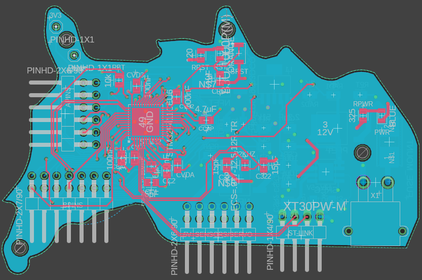
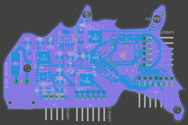
Our PCB design consists of 4 layers: 2 interiors for GND (light blue layer) and 3v3 Power (purple layer), a top layer for the STM MCU and its necessary components (red traces), and a bottom layer for power regulation (dark blue traces). A clearer view of the components and their connections can be seen in the below schematic of the PCB.
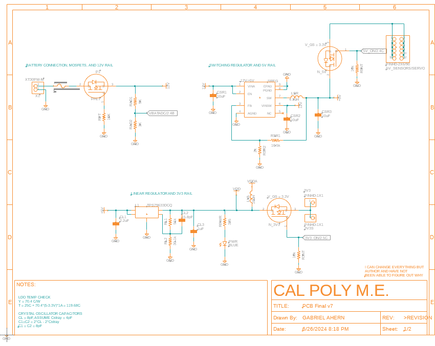
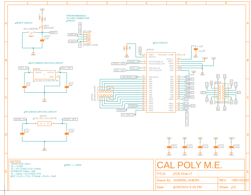
The reason why we put components on both the top and bottom layers was to reduce the overall dimensions of the board and conserve space inside the robot. While this did yield a much smaller footprint, it made it difficult to solder components as we could not just use a template for all; we were able to use a template for the components on the top layer, but had to hand-solder the bottom layer components. The conversion of the 12V input down to 5V and then again to 3V3 was done because the battery we used supplied 12V, most of our sensors and motors required 5V, and our STM (as well as a couple other sensors) needed 3V3. We also chose to shape it like the United States for aesthetics.
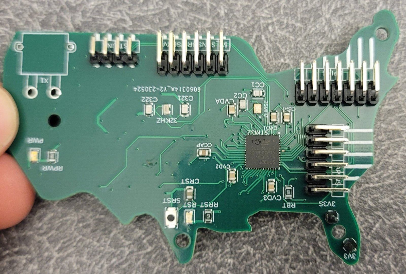
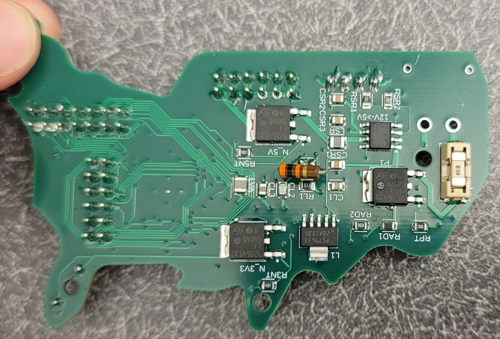
After all our components came in, we realized that we were missing one of our resistors. Due to lack of time, we were unable to order a replacement. However, we were able to use one of the through-hole resistors in the mechatronics lab as a replacement; we soldered on a through-hole resistor to the SMD pads as an emergency fix.
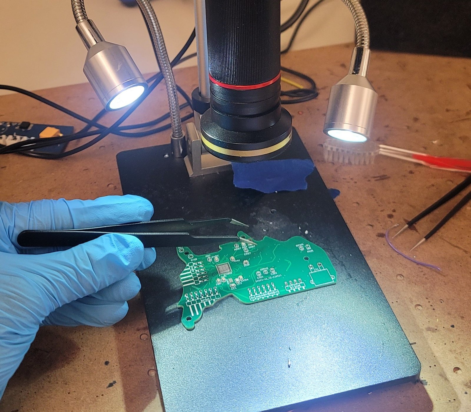
After soldering our components to our pcb we found that the 5V and 3v3 rails were outputting the correct voltage, but the Power LED (Orange LED on the top of the board designed to indicate that power is connected) was not on. While probing the components on the power side of the board, we forgot to disconnect the power supply and accidentally caused a short in the board. Although we replaced the switching and linear regulators (the switching was shorted during probing and the linear was suspected of potentially not being entirely connected since the Power LED was not lit) and found that all power regulators were continuous (checked using the continuity feature on a multimeter), we were unable to find and correct the short in time. We suspect that either the board itself became damaged or that one of the other SMD components was shorted. Because of this, we switched back to the Blackpill for the remainder of the project.
Major Hardware - Sensors:
While we initially intended on using a color sensor, IR sensors, motor encoders, and an accelerometer to perform line following, ball/bot/arena detection, and keep track of our bot's location in the arena, we ended up deciding to use the overhead camera and its visual processing code - provided by Nathan - and proximity sensors for movement and location tracking. We did keep the color sensor, however, and aimed to use it to confirm that all balls collected were the correct color.
Software - Drivers
Color Sensor Driver:
DISCLAIMER: The current version of the driver is essentially a paired down version of the TCS3472 driver by ipa64 The color sensor is a TCS34727, which is driven through I2C protocol. Reading from each of the three color registers (red, green, and blue), requires first writing to a master register on the device to specify which color register to pull from, then reading this value into an array on the microcontroller for processing/display etc. This driver was written by interpreting multiple functions from the Adafruit driver for Arduino into equivalent STM32 HAL, largely using the HAL functions HAL_I2C_Master_Transmit() to write to the master register (specifying color register) and HAL_I2C_Master_Receive() to read this data. Later, we discovered a driver made in STM32 HAL by ipa64, and revised our functions to mimic his style, which used the single function HAL_I2C_Mem_Read() instead of the multiline read and write functions we were calling.
Mecanum Wheels/Motor Driver:
The motor drivers used here are very similar to those written for lab 2, the notable exception being that the off-channel is held low instead of high. Apart from this, it is the same PWM setup. The mecanum driver takes in four motor driver objects and controls all PWM simultaneously. Functions include going forward, backward, and each of the side directions. The direction of the wheels is controlled within the motor driver by either sending a positive or negative speed value.
Communication:
Because of the use of an overhead camera as our main sensor for controlling our robot, we developed two external files (one in Python using VSS and another in C++ using the Arduino IDE) to access the camera data, process it to plot a trajectory to the nearest ball of the correct color, then send commands to the Master Mind/main file on the STM MCU over first Bluetooth serial (from our laptop to the ESP32) and then through USART (from the ESP32 to STM). The code for the Bluetooth Serial communication on the ESP32 is simple and is set up to grab the characters sent to it from the laptop and echo them to the STM.
The above video explains the communication setup for the robot.
Code and Data Interpretation:
For more information on how we interpreted the data, and the code for doing so, see our linked, full memo (in the Documents section of the footer) and Github repository below.
